Choosing a Cavity
There is no single cavity design that is clearly superior to all others. The choice of cavity design and materials, instead, depends upon the application. We’ve worked with the leading labs in the world to provide frequency stabilization solutions for a broad range of applications, and can advise on a customized solution for your needs. Factors to consider in choosing the best cavity design for your application include:
- Linewidth required
- Free spectral range (FSR) needed
- Operating environment (temperature & amount of vibration)
- Stability required, both short and long term – degree of tolerable drift
On the whole, all systems for narrow linewidths use a vibration isolation stage, and the thermal noise floor of the cavity can be reached with any geometry (including cylindrical). If the value of that noise floor is important, then a notched cavity, being longest, has the lowest thermal noise floor (assuming a good choice of mirrors for large beam spot size).
Standard Reference Cavity Selection Guide
| CAVITY TYPE |
FSR (GHz) |
APPLICATIONS & PERFORMANCE |
| Cylinder Cavity 100 mm long, 50 mm diameter |
1.5 |
|
| Notched Cavity 100 mm long, 50 mm diameter |
1.5 |
|
| Notched cavity 100 mm long, 100 mm diameter |
1.5 |
|
| Spherical cavity 50 mm diameter |
3 |
|
| Cube cavity 25 mm |
6 |
|
| 200 mm & 300 mm long | 750 MHz/ 500 MHz |
|
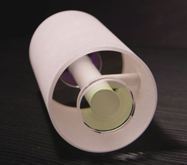
Cylindrical Cavities
Cylindrical cavities feature a tried-and-true geometry for spectroscopy, offering locked laser linewidths at the 10 Hz level. They are the most common cavity design, but other cavity designs offer distinct advantages for some applications.

Notched Cavities
Notched cavities offer reduced acceleration sensitivity as compared to a cylindrical design. Long spacer lengths, from 100 mm up to 300 mm, yield the lowest thermal noise floor and narrowest laser linewidths. We recommend a notched cavity geometry when Hz-level linewidths and low frequency drift are paramount.
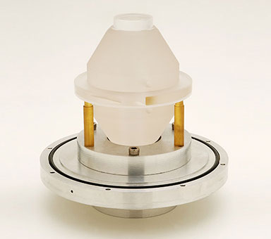
Spherical & Cubic Cavities
Spherical and cube cavities are the most compact cavity designs, while still delivering narrow linewidth performance. These rigidly-held spacers can be moved without need for realignment.
Midplane Cavities
The careful design and mounting of midplane cavities means low vibration sensitivity in the vertical dimension. These cavities can be relocated while preserving alignment.
Temperature Control Considerations
Spherical cavity vacuum housings are compact, and the vacuum housing arrangement allows for milliKelvin stability temperature control over a wide range of temperatures. The temperature control property can be important, as the ULE material for the spacer can have a zero expansion point at any temperature between 2°C and 40°C, so it is possible to operate at that zero expansion point (which is typically a few degrees Celsius cooler than the spacer zero crossing for fused silica mirrors with ULE rings).
Notched cavity vacuum housings operate between 14°C and 40°C, so the few ULE spacers which have zero crossing temperatures less than 14°C need extra cooling power (chilled water through the heatsinks) to reach their optimal operating temperature.
Material Choice: FS vs ULE mirror substrates
Using fused silica (FS) substrates leads to a thermal noise floor ~2x lower than for ULE (ultra-low expansion glass). For almost all applications, ULE is the best choice as it makes for a cavity with the lowest daily drift. Fused silica mirrors are provided with ULE backing rings to reduce the thermal expansion coefficient.
Applications Served
- Atomic clocks (e.g., Yb, Sr, Yb+, Sr+, Hg+, Ca, Ca+)
- Atomic laser cooling and trapping, including dynamic frequency variation
- High-precision spectroscopy
- Optical frequency comb tooth locking
- RF generation for stable time-keeping to the 15th decimal place
- Local oscillators for time or frequency transfer
- Microwave generation
- Laser radar (long coherence time lasers)
- Fiber sensing
- Detection and sensing of optical fiber perturbations
- Time transfer over optical fiber
- Precision laser wavelength tuning
- Optical frequency sweep generation or shifting for cavity drift cancelation